For 5Gmm-wave application scenarios, 3GPP TR38827 defines five-channel models for UMi (Urban Micro) CDL A~E of urban micro-base station and InO (Indoor Office) CDL A~E of indoor micro-base station. The purpose is to build a reconfigurable channel environment in the laboratory and verify the scene performance of base stations and terminals.
In order to achieve the above application scenario test in the laboratory, this test system has a perfect experimental environment such as a millimeter-wave full-band anechoic chamber, three-dimensional reconfigurable probe wall, millimeter-wave antenna, millimeter-wave frequency converter, and high-precision turntable. By accessing 5G core network and base station devices (or using base station emulator), using advanced instruments such as high-end channel simulator, it fully supports 5Gmm-wave mainstream band, supports all millimeter-wave channel fading models of 3GPP, and supports communication performance test of 5G base station, terminal, chip, and other morphological devices.
Using compact field technology, the system works with a base station emulator, spectrum analyzer, signal source, and terminal device to complete radiofrequency consistency test items defined by 3GPP 38521-2.
The millimeter-wave probe antenna of this system complies with the distance and angle layout requirements of 3GPP TR38827 by verifying the following channel model parameters in the test area:
Power Delay Profile (PDP)
Doppler/Temporal correlation
PAS similarity percentage (PSP)
Cross-polarization
Power validation
Finally, the similarity of laboratory channel environment is verified according to the channel verification criteria of 3GPP.

Probe Number | Theta/ZoA [deg] | Phi/AoA [deg] |
1 | 90 | 75 |
2 | 85 | 85 |
3 | 85 | 55 |
4 | 85 | 95 |
5 | 95 | 95 |
6 | 90 | 105 |
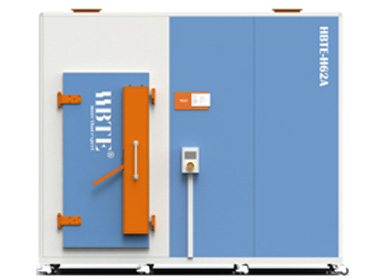
A complete millimeter terminal performance test system includes:
RS Test
Probe wall
Probe antenna
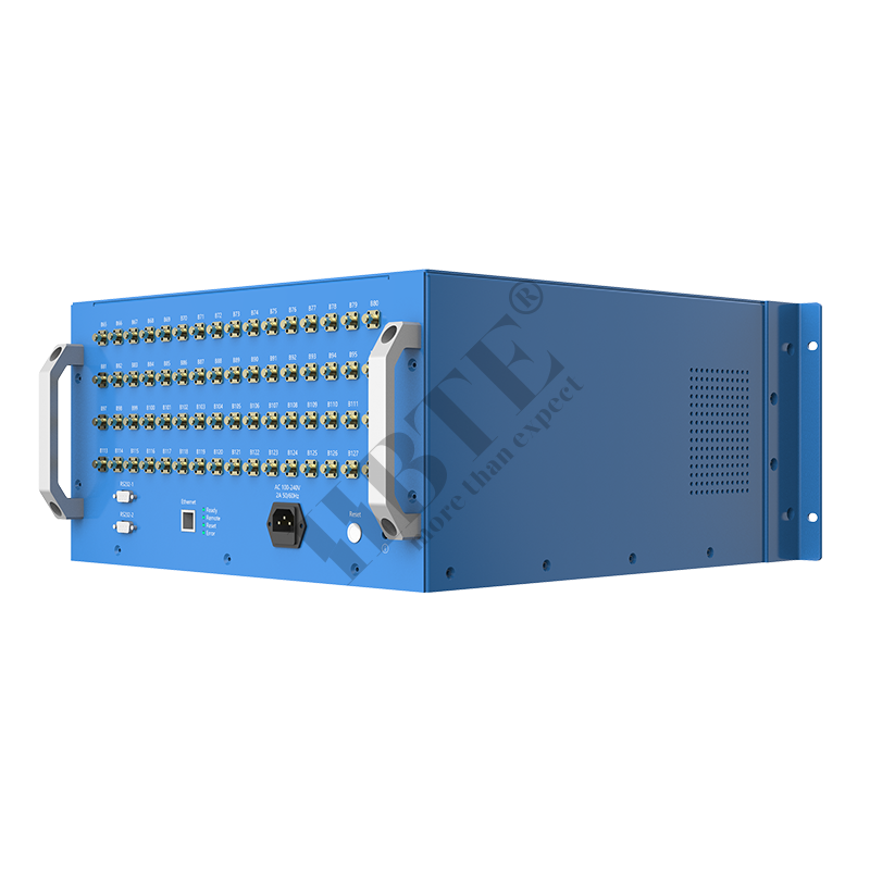
Millimeter-wave frequency converter
Multi-axis turntable
Key features
A single millimeter-wave frequency converter integrates two independent radio frequency channels.
Flexible position of probe antenna;
Integrated design;
Mobile design;

This test system is a turn-key solution. You can test Throughput VS time by simply placing the terminal device on the turntable and configuring the relevant test scenario in the PC interface.
technical parameter
Item | Parameter | Remark |
System | ||
Size | Lm*Wm*Hm(shell) Lm*Wm*Hm(roller) | |
Weight | <2T | |
Frequency | 24~44GHz | |
Shielding effectiveness | >90dB | |
Test area | >20cm | |
Antenna | ||
QTY | 6 | |
Frequency | 24~44GHz | |
Polarization | Bipolarization | |
Port isolation | >30dB | |
VSWR | <1.7 | Typ. |
Gain | 4dBi | Typ. |
Beam width(3dB) | 25°@ | |
Cross Polarization Ratio | >30dB | |
Multi-axis positioner | ||
Axis | 2 | |
Angle range | Azimuth axis: 0 ~ 360 degrees Polarization axis: 0 ~ 360 degrees | |
Angle step | ≥0.1° | |
Angular Precision | <±0.05° | |
Repetition accuracy | <±0.05° | |
Speed | ≤20°/s | |
Bearing | >20kg | |
Millimeterwave Upconverter | ||
RF Frequency | 24~31GHz | |
RF input power | <-5dBm | |
Gain flatness | <1.25dB@BW400MHz | |
IF Frequency | 2~6GHz | |
Switching time | <2us | |
Power adjustment range | 30dB | |
Local-oscillator input power | >0dBm | |
May,08,23
Why Choose the Solid State Switch?
 OTA System
  Product Test Lab
  RF System
  RF shielded Box / Cabinet
  RF Shielded Room / Chamber
  Positoner/Turntable
  Antenna
  Passive Component
  Cable Assembly
  Laboratory Outsourcing Service
  Industrial Internet Software
  Automation Device
  5G Millimeter Wave RF Consistency System
  MIMO OTA
  Millimeter Wave Base Station Performance
  Millimeter Wave Terminal Performance
  WiFi Performance
  5G Conducted MIMO
  Base Station Reverberation Chamber
  Terminal Reverberation Chamber
  CATR
CATR  EMC
EMC  Laboratory Intelligent Monitoring System
  Document Download
  FAQ
FAQ  Our History
  Social Responsibility
  News
News  Career